Schematic 555 Timer Circuit Diagram - FM Generation using 555 Timer : 555 timer astable circuit electrical engineering.. The circuit may be triggered and reset on falling waveforms, and the output circuit can source or sink up to 200ma or drive ttl circuits. The schematic shows (3) circuits, because one circuit does not work well over the entire vcc range. Look at the circuit diagram. 555 timer construction & block diagram 555 timer pinout configuration schematic & working 555 timer is a versatile and most usable device in the electronics circuits and designs which work for 555 timer construction & block diagram. These circuits were developed to provide certain functions that are not.
Some important features of the 555 timer: 555 timer ic remains in stable state until the external triggering is applied. Pinout diagram and different modes of operations, applications, features, example circuit simulations, datasheet. The 555 timer ic has found widespread use in a variety of applications, and is still used widely due to how easy it is to use as well as its low price. There are lots of manufacturers who manufacture 555. 555 timer is used in almost every electronic circuit today. 555 timer, as the name specified, are the electronics circuits used for measuring time intervals. The circuit diagram can be understood with the i am an electronic engineer (dipiete ), hobbyist, inventor, schematic/pcb designer, manufacturer. Here is the list of 40 555 timer circuits that can help you in understanding 555 timer functions.first five circuits explains. The 555 timer can provide time delays ranging from several minutes for one cycle of operation to many thousands of cycles per second. The timer will start when the wire is inserted into the protoboard between these two points, and ignore further contacts. You can watch the following video or read the written tutorial below. An external triggering is required for transition from stable to unstable state.
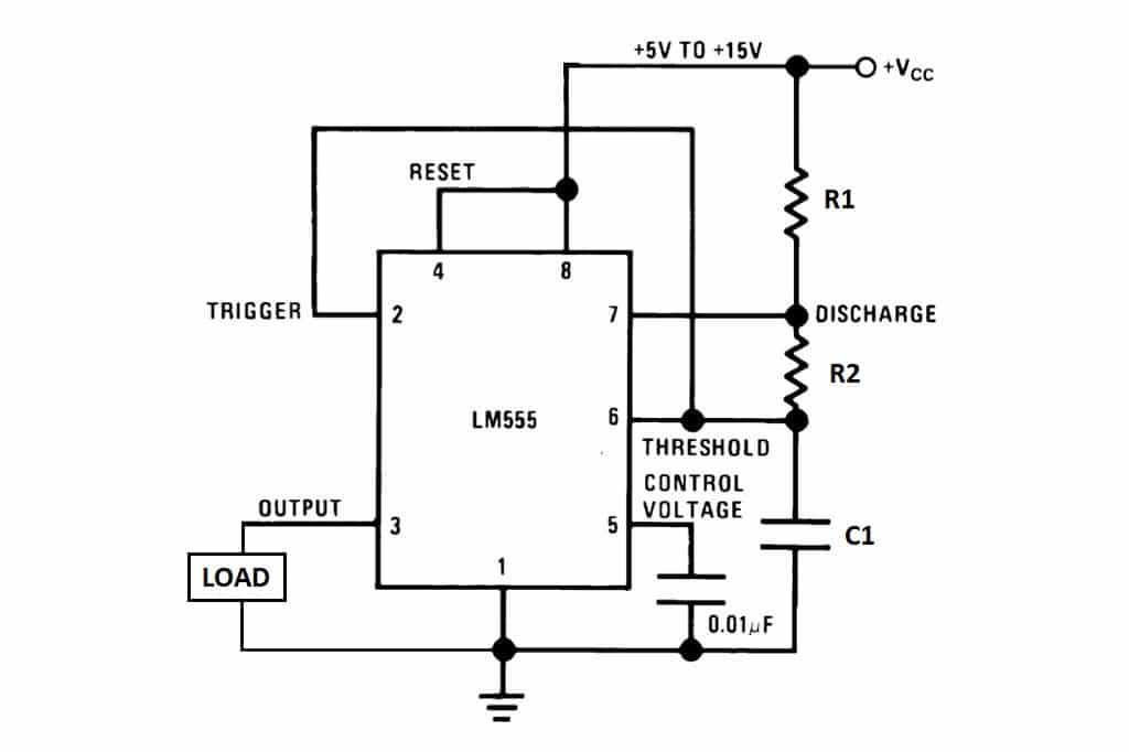
The 555 timer ic becomes invented via signetic organization and it becomes termed as se or ne555 timer ic. The red section is the rc circuit that determines the pulse length. 7 below, you'll see the circuit schematic of the 555 and the parts relevant to it. There are lots of manufacturers who manufacture 555. With this mod, vcc may be increased to the 18v limit.
A complete basic tutorial for 555 timer IC - Electronic ... from 3.bp.blogspot.com In this tutorial we will learn how the 555 timer works, one of the most popular and widely used ics of all time. The 555 timer can provide time delays ranging from several minutes for one cycle of operation to many thousands of cycles per second. Finally, power up your circuit by connecting the battery to your breadboard Here is the list of 40 555 timer circuits that can help you in understanding 555 timer functions.first five circuits explains. In astable mode, the output cycles on and off continuously. A 555 timer has two comparators, which are. The block diagram of a 555 timer is shown in the above figure. The ne555, sa555, and se555 monolithic timing circuits are highly stable controllers capable of producing accurate time delays or oscillation.
With this information you will learn how how the 555 works and will have the experience to build some of the circuits below.
This consists of a few different elements: If you force the timer input to stay low past timeout the output will stay. By adding one or two external resistors and one capacitor the. The second circuit adds d1 to the emitter of q1 in order to increase vebo. 555 timer ic remains in stable state until the external triggering is applied.
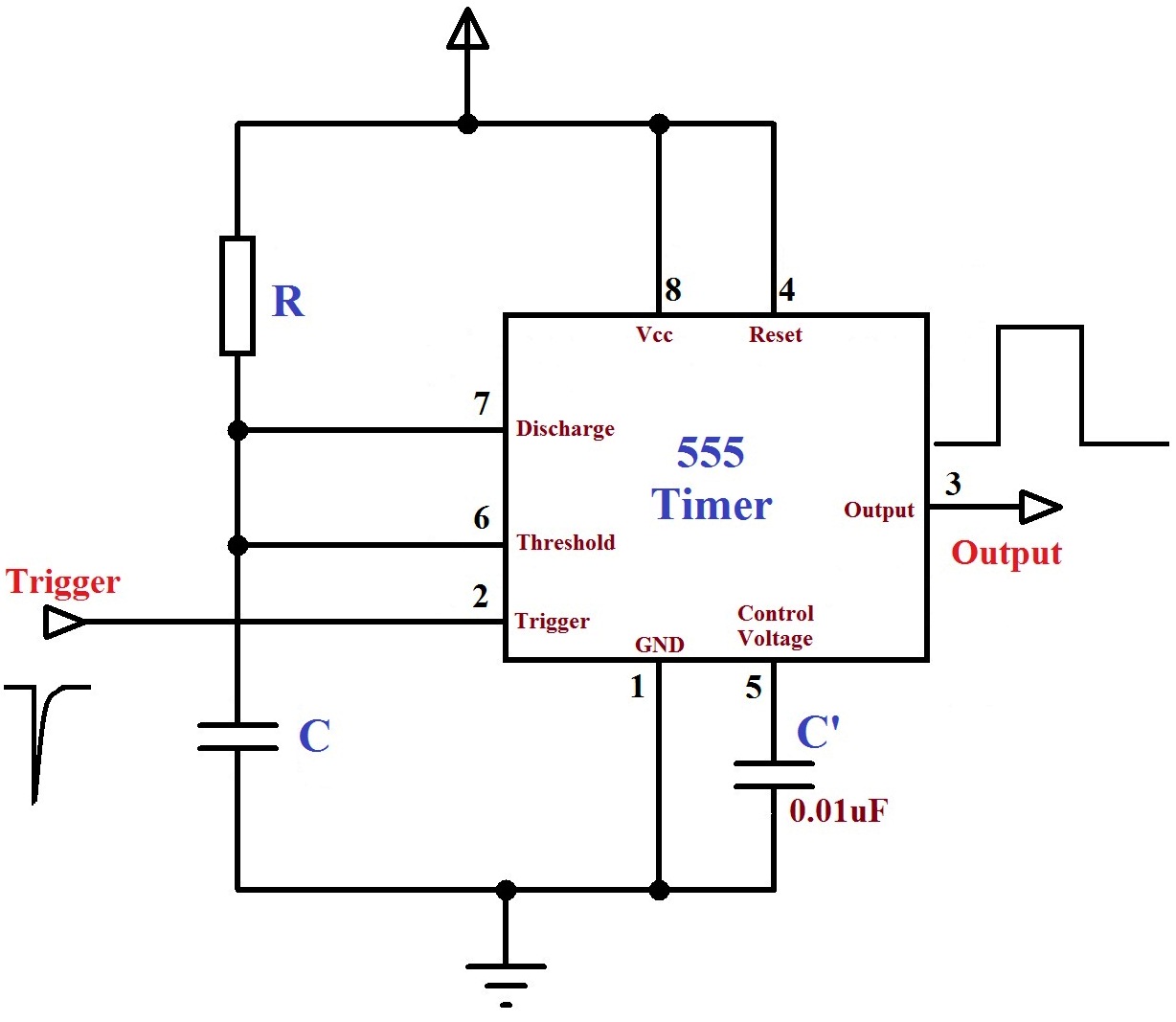
Monstable Multivibrator using 555 Timer from electrosome.com The circuit inside the 555 is just an amplifier with 2 inputs and an output. Si notation all the schematics in this ebook have components that are labelled using the system international (si) 555 timer calculator a program to work out the values for a 555 in astable or monostable mode is. Monostable mode is great for creating. The ne555, sa555, and se555 monolithic timing circuits are highly stable controllers capable of producing accurate time delays or oscillation. 555 timer was first introduced by signetics corporation in 1971 as se555/ne555. Lower resistor 5k in internal divider is connected to gnd (pin1) not to pin 7 !!!! The 555 timer, designed by hans camenzind in 1971. Metal detector circuit using ic 555 and buzzer gadgetronicx.
Metal detector circuit using ic 555 and buzzer gadgetronicx.
The schematic shows (3) circuits, because one circuit does not work well over the entire vcc range 555 timer schematic. The ne555, sa555, and se555 monolithic timing circuits are highly stable controllers capable of producing accurate time delays or oscillation.


0 Komentar